You are here
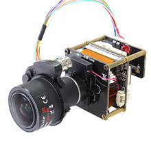
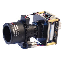
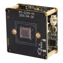
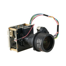
Dual Board
 |  |
 |  |
This product not include cable by default.
| JP1 Power interface | Preview | Pitch | |
| 1 | DC12V |  | 1.25mm |
| 2 | Video GND | ||
| 3 | CVBS output | ||
| 4 | GND | ||
| JE1 Network interface |
| 1.25mm | |
| 1 | RJ45_1 (TX+) | ||
| 2 | RJ45_2 (TX-) | ||
| 3 | RJ45_3 (RX+) | ||
| 4 | RJ45_6 (RX-) | ||
| 5 | Network connection indicator light (green light) | ||
| 6 | Network status indicator light (yellow light) | ||
| Sensor board J1 IR-cut interface | 1.25mm | ||
| 1 | IR-CUT control signal 5V- | ||
| 2 | IR-CUT control signal 5V+ | ||
| Sensor board J2 DC auto Iris interface (Support automatic aperture model: -AI) | Depend on color definition of Lens | 1.25mm | |
| 1 | drive- | ||
| 2 | damp- | ||
| 3 | drive+ | ||
| 4 | damp+ | ||
| Sensor board J3 Power Auto Zoom lens interface (Support Electric lens model:-AZ) | Depend on color definition of Lens | 1.25mm | |
| 1 | Focus A- | ||
| 2 | Focus A+ | ||
| 3 | Zoom A- | ||
| 4 | Zoom A+ | ||
| 5 | Zoom B+ | ||
| 6 | Zoom B- | ||
| 7 | Focus B- | ||
| 8 | Focus B+ | ||
| Sensor board J4 No definition | |||
| J5 Infrared Light board interface | 1.25mm | ||
| 1 | Infrared Light board12V power output | ||
| 2 | GND | ||
| 3 | LED feedback signal input(0.8V-12V) | ||
| 4 | Infrared Light enable control | ||
| J6 function interface | Support powerless microphone and Line in | 1.25mm | |
| 1 | Audio in | ||
| 2 | Audio GND | ||
| 3 | Audio out | ||
| 4 | GND | ||
| 5 | Reset | ||
| 6 | Alarm in 1, low level effective | ||
| 7 | Alarm in 2 (reserve), low level effective | ||
| 8 | Alarm out control GPO, 3.3V level signal | ||
| 9 | RS_485+ | ||
| 10 | RS_485- | ||
| JU1 USB interface | Support MT7601 /RT5370 USB wifi module. | 1.25mm | |
| 1 | GND | ||
| 2 | USB_DP | ||
| 3 | USB_DM | ||
| 4 | 5V power out | ||
| J7 expandion board | FPC | ||
| 1 | USB_DP | ||
| 2 | USB_DM | ||
| 3 | System | ||
| 4 | SDIO Work Clock | ||
| 5 | SDIO Data3 | ||
| 6 | SDIO Data2 | ||
| 7 | SDIO Data1 | ||
| 8 | SDIO Data 0 | ||
| 9 | System | ||
| 10 | SDIO Order | ||
| 11 | SDIO Power enable control signal | ||
| 12 | SDIO Card detection signal | ||
| 13 | SDIO Pull-up resistor power out | ||
| 14 | Alarm out control GPO | ||
| 15 | System | ||
| 16 | DC5V Power out | ||