You are here
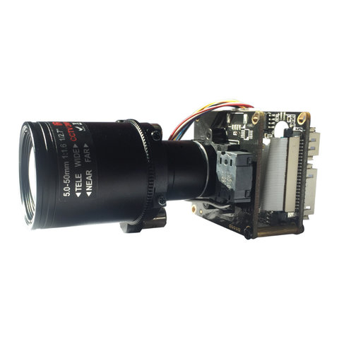
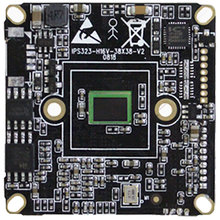
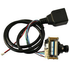
IP16XS323D-AZ0550 1/2.9" 2MP 1080P Sony IMX323 + HI3516CV300 H.265 IP Camera Module board 5-50mm Auto Zoom Lens (2MP, IMX323)
Description
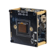
1/2.9" IMX323 low illumination CMOS sensor
Adopt Hi3516CV300, Standard size:38mm*38mm Dual Board
support Day& Night switch infrared sensor, Support LDR signal linkage, apply to common Box, Bullet, dome and etc housing
H.265/H.264 video coding, support dual stream, Max resolution:1920*1080, color 0.1Lux@F1.2 B& W0.01 Lux@F1.2
Support onvif 2.4 protocol, Support compatible with most oversea and local platform software manager system
| Model No | IP16XS323D-AZ27135(2.0MP) | |
| Hardware | ||
| Chipset | HI3516CV300 1/2.9" CMOS IMX323 | |
| Min illumination | Color 0.1Lux@F1.2 B& W0.01Lux@F1.2 | |
| SNR | > 50db(AGC OFF) | |
| WDR | DWDR > 80db | |
| Lens Type | 10X Optical auto zoom Lens 5-50mm | |
| interface | ||
| Audio/ Talk input | 1CH Audio MIC input/ line input | |
| Audio output | 1CH line output | |
| Analog video output | support 1ch CVBS output | |
| Alarm in/out | 1ch alarm in | |
| IO interface | 1ch reset | |
| USB interface | 1pcs USB interface, support TF card storage expansion(MAX128G) | |
| Video coding | ||
| Coding format | H.265 Main Profile coding H.264 Baseline, Main Profile, High Profile coding | |
| MJPEG coding | ||
| Image Resolution | Main stream | 1920*1080, 1-25(30)fps 1280*720, 1-25(30)fps |
| Sub-stream | 704*576, 1-25(30)fps 640*480, 1-25(30)fps | |
| 640*352, 1-25(30)fps 320*240, 1-25(30)fps | ||
| video compression rate | 32Kbps-16Mbps able to continue adjusting, support CBR/VBR | |
| Subtitles overlay | support channel name, date time, streaming info overlay, overlay position adjustable | |
| Data transmission & storage | ||
| Data storage | video, image files | |
| Storage mechanism | Manual, auto(circulation, time, alarming switch volume,motion detection) | |
| Alarm data transmission | FTP, E-mail,browser, manage software | |
| Protocol support | TCP/IP, UDP, RTP, RTSP, TRCP, HTTP, DNS, DDNS, DHCP, FTP, NTP, PPPOE, SMTP, UPNP | |
| ONVIF protocol | Standard onvif 2.4protocol | |
| Client browser | Support IE6.0 and above(embedded Web Server in device)browse by browser,support 8 users to access simultaneously(MAX) | |
| Mobile client | Support iPhone, iPad, Android | |
| General Specification | ||
| Power supply | DC12V 1A/POE(External connect POE module) | |
| Device power | 3W(MAX) | |
| Device dimension | 38(long) * 38(wide) *15(high)mm (without lens) | |
| IR-CUT pitch of holes | 22mm | |
| Device weight | 0.15Kg | |
Pin Definition
Dual Board
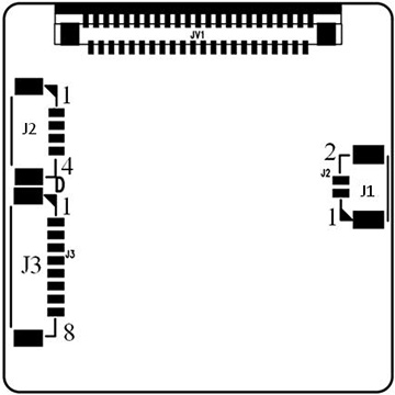
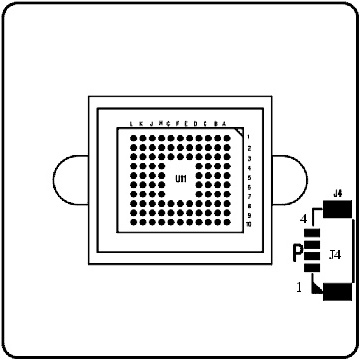
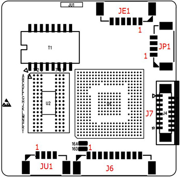
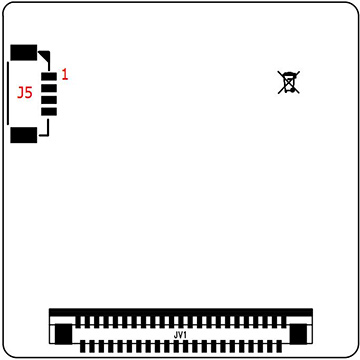
This product not include cable by default.
JP1 Power interface Preview Pitch
1 DC12V 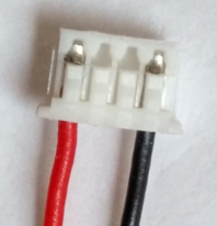
1.25mm 2 Video GND 3 CVBS output 4 GND JE1 Network interface 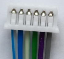
1.25mm 1 RJ45_1 (TX+) 2 RJ45_2 (TX-) 3 RJ45_3 (RX+) 4 RJ45_6 (RX-) 5 Network connection indicator light (green light) 6 Network status indicator light (yellow light) Sensor board J1 IR-cut interface 1.25mm 1 IR-CUT control signal 5V- 2 IR-CUT control signal 5V+ Sensor board J2 DC auto Iris interface (Support automatic aperture model: -AI) Depend on color definition of Lens 1.25mm 1 drive- 2 damp- 3 drive+ 4 damp+ Sensor board J3 Power Auto Zoom lens interface (Support Electric lens model:-AZ) Depend on color definition of Lens 1.25mm 1 Focus A- 2 Focus A+ 3 Zoom A- 4 Zoom A+ 5 Zoom B+ 6 Zoom B- 7 Focus B- 8 Focus B+ Sensor board J4 No definition J5 Infrared Light board interface 1.25mm 1 Infrared Light board12V power output 2 GND 3 LED feedback signal input(0.8V-12V) 4 Infrared Light enable control J6 function interface Support powerless microphone and Line in 1.25mm 1 Audio in 2 Audio GND 3 Audio out 4 GND 5 Reset 6 Alarm in 1, low level effective 7 Alarm in 2 (reserve), low level effective 8 Alarm out control GPO, 3.3V level signal 9 RS_485+ 10 RS_485- JU1 USB interface Support MT7601 /RT5370 USB wifi module.
Support -ET TF card extension board.1.25mm 1 GND 2 USB_DP 3 USB_DM 4 5V power out J7 expandion board FPC 1 USB_DP 2 USB_DM 3 System 4 SDIO Work Clock 5 SDIO Data3 6 SDIO Data2 7 SDIO Data1 8 SDIO Data 0 9 System 10 SDIO Order 11 SDIO Power enable control signal 12 SDIO Card detection signal 13 SDIO Pull-up resistor power out 14 Alarm out control GPO 15 System 16 DC5V Power out
Shipping
Remark:
For orders with a high total amount, please choose DHL, EMS other than Airmail, ePacket.
For orders with a high total amount, please choose DHL, EMS other than Airmail, ePacket.
Specification
- SKU:
- IP16XS323D-AZ0550
- Resolution:
- 2MP 1080P
- Sensor:
- IMX323

