You are here
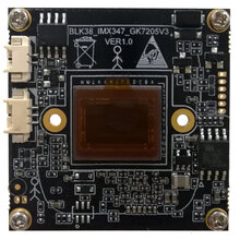
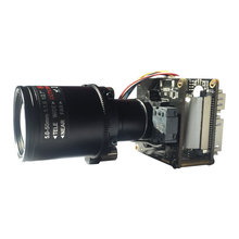
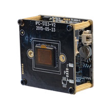
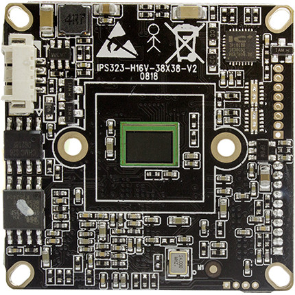
IP16XS323 Sony IMX323 Hi3516CV300 2MP 1080P H.265 IP Camera board Security Camera module (2MP, 20mm, IMX323)
Description
Hi3516CV300 Sony IMX323 2MP H.265 IP Camera module board
Feature:
Support HKvision protocol (iVMS4200 and NVR)
Ultra low power consumption
Support WIFI(default MT7601)/TF(128GB) via USB
Support 1 channel Audio input & Audio output
Sony IMX323 module product advantages
Using Huawei's high-end video processing chip, support H.265 video compression algorithm
With Sony image sensor, image quality is better, with better low illumination
2MP ultra-low power consumption, less heat
Support HKvision private agreement, the use of Hislicon 4200 platform software directly search and management
The auto iris function is supported by default
The default support for audio input and output functions, the default without a lens
| 2MP Hi3516CV300 + IMX323 specifications (H.265) | |
| Module information | Default username: admin Password: admin IP: 192.168.1.88 Mobile phone monitoring software: Danale |
| Sensor part | |
| chipset | Hi3516CV300 + IMX323 [Ultra Low Power] |
| sensor | 1 / 2.9 "Sony IMX323 CMOS sensor |
| Minimum illumination | Color 0.01Lux@F1.2 |
| Signal to noise ratio | > = 50db (AGC OFF) |
| Wide dynamic range | > 80db |
| Main chip encoding section | |
| Encoding type | H.264 encoding MJPEG encoding |
| Bit rate size | Adjustable 32kbps-8Mbps, fixed stream and variable stream (CBR & VBR) |
| Video frame rate | PAL: 1-25fps NTSC: 1-30fps adjustable |
| Main video stream | 1920 * 1080, 1280 * 960, 1280 * 720 |
| Secondary video stream | 704 * 576, 640 * 480,640 * 352, 320 * 240 |
| Interface Protocol | Standard ONVIF2.4 and GB28181 protocols |
| Network protocol | TCP / IP, UDP, RTP, RTSP, RTCP, HTTP, DNS, DDNS, DHCP, FTP, NTP, PPPOE, SMTP, UPNP |
| Network Interface | RJ45 10M / 100M adaptive Ethernet port |
| USB interface | Support extended 4G or wifi, TF card maximum support 64G |
| audio port | 1 channel audio MIC linear input 1 channel audio output |
| Storage type | Manual, automatic (cycle, timing, alarm switch, motion detection) |
| Alarm data transmission | Support FTP, Email, browser, management software output |
| Number of visits | Support 8 users at the same time online browsing |
| Other functions | |
| working environment | -10 ~ +60 ° C, Humidity: 10% to 90% |
| power input | DC 12V / 2A or POE power supply (expandable) |
| Power consumption | < = 3W |


| JP4 Power interface | |
| 1 | DC12V |
| 2 | CVBS GND |
| 3 | CVBS Signal Output |
| 4 | GND |
| J6 Network interface | |
| 1 | RJ45_1 (TX+) |
| 2 | RJ45_2 (TX-) |
| 3 | RJ45_3 (RX+) |
| 4 | RJ45_6 (RX-) |
| 5 | Network connection indicator (green) |
| 6 | Network status indicator (yellow) |
| J1 IR-cut interface | |
| 1 | IR-CUT control signal 12V |
| 2 | IR-CUT control signal 12V |
| J3 infrared light board interface | |
| 1 | Infrared light board 12V power supply output |
| 2 | GND |
| 3 | Infrared feedback signal input (threshold 0.8V-12V) |
| 4 | Infrared light enable control |
| J2 function interface | |
| 1 | Audio input |
| 2 | Audio ground |
| 3 | Audio output |
| 4 | Reset |
| 5 | Ground |
| 6 | USB_DP |
| 7 | USB_DM |
| 8 | 5V power supply output |
| 9 | Alarm output |
| 10 | Alarm input |
Pin Definition
Single Board H.265 Full function


No. Pin Defination Pitch Preview JP4 Power interface 1.25mm 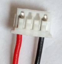
1 DC12V 2 Video GND 3 CVBS Signal Out 4 GND J6 Network interface 1.25mm 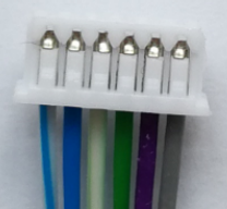
1 RJ45_1 (TX+) 2 RJ45_2 (TX-) 3 RJ45_3 (RX+) 4 RJ45_6 (RX-) 5 Network connector light(Green) 6 Network status light(Yellow) J1 IR-cut interface 1.25mm 1 IR-CUT control signal 12V- 2 IR-CUT control signal 12V+ J3 LED Board interface 1.25mm 1 LED board 12V power out 2 GND 3 LED feedback signal (0.8V-12V) 4 Infrared light enable control J2 Function interface 1.25mm 1 Audio in 2 Audio GND 3 Audio out 4 Reset 5 GND 6 USB_DP 7 USB_DM 8 5V power out 9 alarm out I/O(3.3V Level signal) 10 Alarm in