You are here
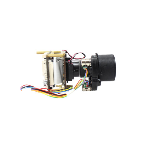
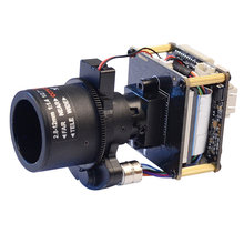
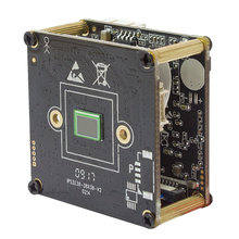
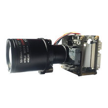
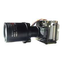
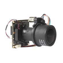
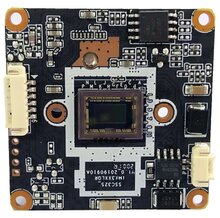
IP16DS327D-AZ27135 1/2.8" 2MP 1080P Sony IMX327 + HI3516D IP 2.7-13.5mm Auto Zoom Starlight Security CCTV HD Camera Module board
Description
2MP WDR 2 Boards IP Camera Module, Hi3516D + SONY Starvis IMX327 CMOS
1/2.8" 2.0 Megapixels Progressive Scan Sony IMX327 CMOS, Hisilicon Hi3516D Chipset, the highestresolution of 1920*1080, 0.001 Lux@F1.2 (color)
38X38mm 2 boards
RS485,OptionalMotorized lens, IR - CUT (day/night), adapt Bullet, Dome
H.264 or H.265 video coding, double stream, ONVIF2.4, be compatible many NVR and platform management software.
Hisilicon Hi3516D
1/2.8" 2.0 Megapixels Progressive Scan Sony IMX290 CMOS
Max 25/30fps@2.0 Megapixels (1920*1080)
H.264/H.265 & MJPEG dual-stream encoding
WDR> 120dB
Privacy Mask, Motion Detection
Support Onvif 2.4 protocol
BLC
Model | IP16DS327D-AZ27135 |
| Camera | |
Image Sensor | 1/2.8" 2MP Progressive Scan Sony Starvis IMX327 CMOS |
CPU | Hisilicon 3516D |
Effective Pixels | 1920(H)*1080(V) |
Scanning System | Progressive |
Electronic Shutter Speed | Auto (1/25 ~ 1/10000s) |
Min. Illumination | Color: 0. 001Lux@F1.2 |
S/N Ratio | ≥50db(AGC OFF) |
| Camera Features | |
Day/Night | Auto(ICR)/Color/B/W |
WDR | >120dB |
White Balance | Auto |
Gain Control | Auto |
Noise Reduction | 3D |
Privacy Masking | Up to 4 areas |
| Lens Type | 5X Optical zoom lens, 2.7-13.5mm 2MP |
| Video | |
Compression | H.264/MJPEG/H.265 |
Resolution | 1080P(1920*1080) / 720P(1280*720) / D1(704*576) / VGA(640*480) / QVGA(320*240) |
Main Stream | 1920*1080(1 ~ 25/30fps), 1280*720(1 ~ 25/30fps) |
Sub Stream | D1/VGA/QVGA(1 ~ 25/30fps) |
Bit Rate | 32KB ~16Mbps, support VBR, CBR |
Text Overlay | Channel, Date & Time, Bit Rate |
| Network | |
Data Storage | Video record, Picture format |
Trigger | Manual, Automatic(motion detection, alarm, schedule, cycle ) |
Alarm data transmission | FTP, E-mail, Browser, CMS |
Protocol | TCP/IP, UDP, RTP, RTSP, TRCP, HTTP, DNS, DDNS, DHCP, FTP, NTP, PPPOE, SMTP, UPNP |
ONVIF | ONVIF 2.4 |
Max. User Access | 8 users, IE, Google, Firefox |
Smart Phone | Windows Mobile, iPhone, iPad, Android |
| Auxiliary Interface | |
Audio in | Support |
Audio out | Support |
BNC Video out | Support |
RS422/RS485 | Support |
USB | Support (Optional MT7601 WiFi/128G USB flash) |
Alarm in | Support |
Alarm out | N/A |
IO Interface | Support |
| General | |
Power Supply | DC12V / PoE (802.3af) |
Power Consumption | <3W |
Working Environment | -20°C~+55°C , Less than 90% RH |
Dimensions | 38 x 38 x 70mm |
Weight | 0.15kg |
Pin Definition
Dual Board
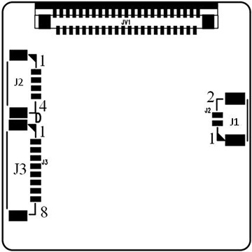
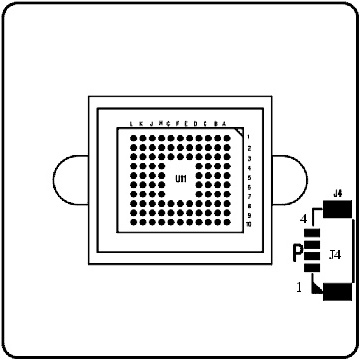
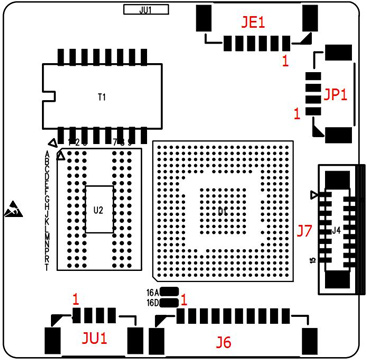
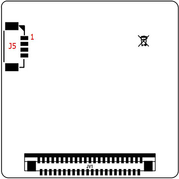
This product not include cable by default.
JP1 Power interface Preview Pitch
1 DC12V 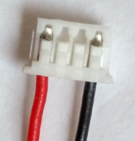
1.25mm 2 Video GND 3 CVBS output 4 GND JE1 Network interface 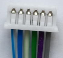
1.25mm 1 RJ45_1 (TX+) 2 RJ45_2 (TX-) 3 RJ45_3 (RX+) 4 RJ45_6 (RX-) 5 Network connection indicator light (green light) 6 Network status indicator light (yellow light) Sensor board J1 IR-cut interface 1.25mm 1 IR-CUT control signal 5V- 2 IR-CUT control signal 5V+ Sensor board J2 DC auto Iris interface (Support automatic aperture model: -AI) Depend on color definition of Lens 1.25mm 1 drive- 2 damp- 3 drive+ 4 damp+ Sensor board J3 Power Auto Zoom lens interface (Support Electric lens model:-AZ) Depend on color definition of Lens 1.25mm 1 Focus A- 2 Focus A+ 3 Zoom A- 4 Zoom A+ 5 Zoom B+ 6 Zoom B- 7 Focus B- 8 Focus B+ Sensor board J4 No definition J5 Infrared Light board interface 1.25mm 1 Infrared Light board12V power output 2 GND 3 LED feedback signal input(0.8V-12V) 4 Infrared Light enable control J6 function interface Support powerless microphone and Line in 1.25mm 1 Audio in 2 Audio GND 3 Audio out 4 GND 5 Reset 6 Alarm in 1, low level effective 7 Alarm in 2 (reserve), low level effective 8 Alarm out control GPO, 3.3V level signal 9 RS_485+ 10 RS_485- JU1 USB interface Support MT7601 /RT5370 USB wifi module.
Support -ET TF card extension board.1.25mm 1 GND 2 USB_DP 3 USB_DM 4 5V power out J7 expandion board FPC 1 USB_DP 2 USB_DM 3 System 4 SDIO Work Clock 5 SDIO Data3 6 SDIO Data2 7 SDIO Data1 8 SDIO Data 0 9 System 10 SDIO Order 11 SDIO Power enable control signal 12 SDIO Card detection signal 13 SDIO Pull-up resistor power out 14 Alarm out control GPO 15 System 16 DC5V Power out
Shipping
For orders with a high total amount, please choose DHL, EMS other than Airmail, ePacket.
Specification
- SKU:
- IP16DS327D-AZ27135
- Resolution:
- 2MP 1080P
- Sensor:
- IMX327

