You are here
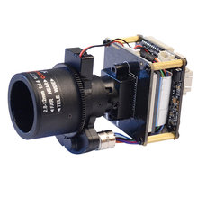
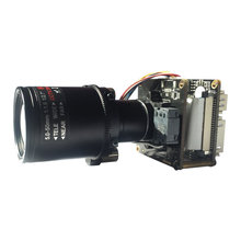
IP16XS327 1/2.8" 2MP 1080P Sony IMX327 Hi3516CV300 H.265 IP Starlight Security CCTV HD Camera Module board (Fixed, 2MP, 20mm, IMX327)


Description
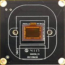
1/2.8 inch 2.0 MP Sony starvis IMX327 CMOS sensor
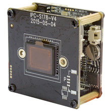
Base on Hi3516CV300 solution
single board size:38mm*38mm
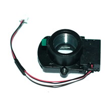
support ICR (IR-CUT), Support photoresistor signal linkage
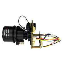
This board use for box camera, bullet camera, Infrared dome camera
H.264/H.265 video coding, dual stream, Max resolution:1920*1080, color:0.001Lux@F1.2, star light with full color.
| Model | IP16XS327(2.0MP) |
| Hardware | |
| CPU | Hi3516CV300, 1/2.8" SONY IMX327 COMS sensor |
| Min illuminator | Color:0.001Lux@F1.2 |
| S/N Ratio | ≥50dB(AGC OFF) |
| WDR | D-WDR > 120db |
| Interface | |
| Audio/talkback input | 1ch MIC in/line in |
| Audio out | 1ch audio out |
| CVBS | Support |
| I/O in/out | Non-support |
| IO interface | 1ch reset |
| USB interface | 1 ch USB interface, TF card slot(max 128G) |
| Video coding | |
| Coding | H.265 Main Profile H264, Baseline/Main Profile/High Profile |
| Resolution | |
| Main Stream | 1920*1080, 1-25(30)fps/s |
| 1280*720, 1-25(30)fps/s | |
| Sub Stream | 704*576, 1-25(30)fps/s 640*480, 1-25(30)fps/s |
| 640*352, 1-25(30)fps/s 320*240, 1-25(30)fps/s | |
| bit rate | 32Kbps-16Mbps, support CBR/VBR |
| OSD Setting | channel name, date and time, stream information superposition, stacking position adjustable |
| Date transmission and storage | |
| Data storage | Video,Image file |
| Storage mechanism | Manual, auto(cycling, timing, alarm on/off, motion detection) |
| Alarm data trans | FTP, E-mail, browser, manage software |
| Protocol | TCP/IP, UDP, RTP, RTSP, RTCP, HTTP, DNS, DDNS, DHCP, FTP, NTP, PPPOE, SMTP, UPNP |
| Wireless protocol | 802.11b/g/n, support WEP, WPA, WPA2 encryption protocol |
| ONVIF | ONVIF2.4 |
| Client browsing | Up to IE6.0 (built-in Web Server)browser, max 4 user |
| Client APP | iPhone, iPad, Android |
| General | |
| Power supply | DC12V 1A/POE(POE optional) |
| Power consumption | 2W(MAX) |
| Device size | 38(L) * 38(W) *15(H)mm(without lens) |
| IR-CUT hole | 20mm |
| |
JP4 Power interface | |
| 1 | DC12V |
| 2 | Video GND |
| 3 | CVBS Out |
| 4 | GND |
J6 Network interface | |
| 1 | RJ45_1 (TX+) |
| 2 | RJ45_2 (TX-) |
| 3 | RJ45_3 (RX+) |
| 4 | RJ45_6 (RX-) |
| 5 | Network connector(Green) |
| 6 | Network status(Yellow) |
| J1 IR-cut interface | |
| 1 | IR-CUT control signal 12V |
| 2 | IR-CUT control signal 12V |
| J3 LED Board interface | |
| 1 | LED board 12V power out |
| 2 | GND |
| 3 | LED feedback signal (0.8V-12V) |
| 4 | Infrared light enable control |
| J2 Function interface | |
| 1 | Audio in |
| 2 | Audio GND |
| 3 | Audio out |
| 4 | Reset |
| 5 | GND |
| 6 | USB_DP |
| 7 | USB_DM |
| 8 | 5V power out |
| 9 | alarm out GPO(3.3V Level signal) |
| 10 | Alarm in GPO |

Pin Definition
Single Board H.265 Full function


No. Pin Defination Pitch Preview JP4 Power interface 1.25mm 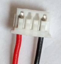
1 DC12V 2 Video GND 3 CVBS Signal Out 4 GND J6 Network interface 1.25mm 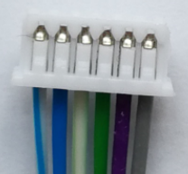
1 RJ45_1 (TX+) 2 RJ45_2 (TX-) 3 RJ45_3 (RX+) 4 RJ45_6 (RX-) 5 Network connector light(Green) 6 Network status light(Yellow) J1 IR-cut interface 1.25mm 1 IR-CUT control signal 12V- 2 IR-CUT control signal 12V+ J3 LED Board interface 1.25mm 1 LED board 12V power out 2 GND 3 LED feedback signal (0.8V-12V) 4 Infrared light enable control J2 Function interface 1.25mm 1 Audio in 2 Audio GND 3 Audio out 4 Reset 5 GND 6 USB_DP 7 USB_DM 8 5V power out 9 alarm out I/O(3.3V Level signal) 10 Alarm in